Lunar Roving Vehicle facts for kids
Quick facts for kids Lunar Roving Vehicle |
|
|---|---|
|
|
| Overview | |
| Manufacturer | |
| Also called |
|
| Designer |
|
| Powertrain | |
| Electric motor | Four .25-horsepower (0.19 kW) series-wound DC motors |
| Transmission | Four 80:1 harmonic drives |
| Battery | Two silver-oxide, 121 A·h |
| Range | 57 miles (92 km) |
| Dimensions | |
| Wheelbase | 7.5 ft (2.3 m) |
| Length | 10 ft (3.0 m) |
| Height | 3.6 feet (1.1 m) |
| Weight |
|
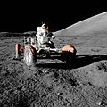
The Lunar Roving Vehicle (LRV) is a battery-powered four-wheeled rover used on the Moon in the last three missions of the American Apollo program (15, 16, and 17) during 1971 and 1972. It is popularly called the Moon buggy, a play on the term "dune buggy".
Built by Boeing, each LRV has a mass of 462 pounds (210 kg) without payload. It could carry a maximum payload of 970 pounds (440 kg), including two astronauts, equipment, and cargo such as lunar samples, and was designed for a top speed of 6 miles per hour (9.7 km/h), although it achieved a top speed of 11.2 miles per hour (18.0 km/h) on its last mission, Apollo 17.
Each LRV was carried to the Moon folded up in the Lunar Module's Quadrant 1 Bay. After being unpacked, each was driven an average of 30 km, without major incident. These three LRVs remain on the Moon.
Contents
Features and specifications
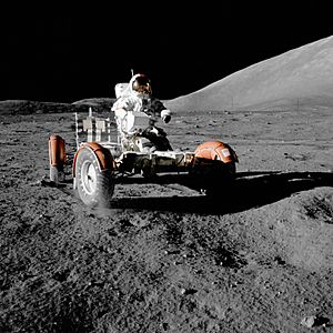
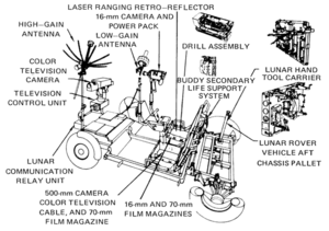
The Apollo Lunar Roving Vehicle is a battery electric vehicle designed to operate in the low-gravity vacuum of the Moon and to be capable of traversing the lunar surface, allowing the Apollo astronauts to extend the range of their surface extravehicular activities. Three LRVs were used on the Moon: one on Apollo 15 by astronauts David Scott and Jim Irwin, one on Apollo 16 by John Young and Charles Duke, and one on Apollo 17 by Eugene Cernan and Harrison Schmitt. The mission commander served as the driver, occupying the left-hand seat of each LRV. Features are available in papers by Morea, Baker, and Kudish.
Mass and payload
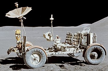
The Lunar Roving Vehicles have a mass of 460 pounds (210 kg), and were designed to hold an additional payload of 510 pounds (230 kg). This resulted in weights in the approximately one-sixth g on the lunar surface of 77 pounds-force (35 kgf) empty (curb weight) and 160 pounds-force (73 kgf) fully loaded (gross vehicle weight). The vehicle frame is 10 feet (3.0 m) long with a wheelbase of 7.5 feet (2.3 m). The height of the vehicles is 3.6 feet (1.1 m). The frame is made of 2219 aluminium alloy tubing welded assemblies and consisted of a three-part chassis that was hinged in the center so it could be folded up and hung in the Lunar Module Quadrant 1 bay, which was kept open to space by omission of the outer skin panel. They have two side-by-side foldable seats made of tubular aluminium with nylon webbing and aluminum floor panels. An armrest was mounted between the seats, and each seat had adjustable footrests and a Velcro-fastened seat belt. A large mesh dish antenna was mounted on a mast on the front center of the rover. The suspension consists of a double horizontal wishbone with upper and lower torsion bars and a damper unit between the chassis and upper wishbone. Fully loaded, the LRV has a ground clearance of 14 inches (36 cm).
Wheels and power
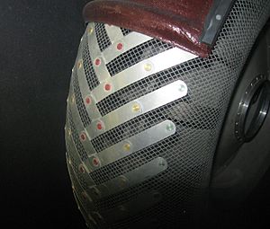
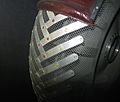
The wheels were designed and manufactured by General Motors Defense Research Laboratories in Santa Barbara, California. Ferenc Pavlics was given special recognition by NASA for developing the "resilient wheel". They consisted of a spun aluminum hub and a 32-inch (81 cm) diameter, 9-inch (23 cm) wide tire made of zinc-coated woven 0.033-inch (0.84 mm) diameter steel strands attached to the rim. Titanium chevrons covered 50% of the contact area to provide traction. Inside the tire was a 25.5-inch (65 cm) diameter titanium bump stop frame to protect the hub. Dust guards were mounted above the wheels. Each wheel had its own electric drive made by Delco, a brushed DC electric motor capable of 0.25 horsepower (190 W) at 10,000 rpm, attached to the wheel via an 80:1 harmonic drive, and a mechanical brake unit. In the case of drive failure, astronauts could remove pins to disengage the drive from the wheel, allowing the wheel to spin freely.
Maneuvering capability was provided through the use of front and rear steering motors. Each series-wound DC steering motor was capable of 0.1 horsepower (75 W). The front and rear wheels could pivot in opposite directions to achieve a tight turning radius of 10 feet (3 m), or could be decoupled so only front or rear would be used for steering. The wheels were linked in Ackermann steering geometry, where the inside tires have a greater turn angle than the outside tires, to avoid sideslip.
Power was provided by two 36-volt silver-zinc potassium hydroxide non-rechargeable batteries developed by Eagle-Picher with a charge capacity of 121 A·h each (a total of 242 A·h), yielding a range of 57 miles (92 km). These were used to power the drive and steering motors and also a 36-volt utility outlet mounted on the front of the LRV to power the communications relay unit or the TV camera. LRV batteries and electronics were passively cooled, using change-of-phase wax thermal capacitor packages and reflective, upward-facing radiating surfaces. While driving, radiators were covered with mylar blankets to minimize dust accumulation. When stopped, the astronauts would open the blankets, and manually remove excess dust from the cooling surfaces with hand brushes.
A T-shaped hand controller situated between the two seats controlled the four drive motors, two steering motors, and brakes. Moving the stick forward powered the LRV forward, left and right turned the vehicle left or right, and pulling backwards activated the brakes. Activating a switch on the handle before pulling back would put the LRV into reverse. Pulling the handle all the way back activated a parking brake. The control and display modules were situated in front of the handle and gave information on the speed, heading, pitch, and power and temperature levels.
Navigation was based on continuously recording direction and distance through use of a directional gyro and odometer and feeding this data to a computer that would keep track of the overall direction and distance back to the LM. There was also a Sun-shadow device that could give a manual heading based on the direction of the Sun, using the fact that the Sun moved very slowly in the sky.
Usage
The LRV was used during the lunar surface operations of Apollo 15, 16 and 17, the J missions of the Apollo program. On each mission, the LRV was used on three separate EVAs, for a total of nine lunar traverses, or sorties. During operation, the Commander (CDR) always drove, while the Lunar Module Pilot (LMP) was a passenger who assisted with navigation.
| Mission | Total distance | Total time | Longest single traverse | Maximum range from the LM |
|---|---|---|---|---|
| Apollo 15 (LRV-1) | 17.25 miles (27.76 km) | 3 h 02 min | 7.75 miles (12.47 km) | 3.1 miles (5.0 km) |
| Apollo 16 (LRV-2) | 16.50 miles (26.55 km) | 3 h 26 min | 7.20 miles (11.59 km) | 2.8 miles (4.5 km) |
| Apollo 17 (LRV-3) | 22.30 miles (35.89 km) | 4 h 26 min | 12.50 miles (20.12 km) | 4.7 miles (7.6 km) |
An operational constraint on the use of the LRV was that the astronauts must be able to walk back to the LM if the LRV were to fail at any time during the EVA (called the "Walkback Limit"). Thus, the traverses were limited in the distance they could go at the start and at any time later in the EVA. Therefore, they went to the farthest point away from the LM and worked their way back to it so that, as the life support consumables were depleted, their remaining walk back distance was equally diminished. This constraint was relaxed during the longest traverse on Apollo 17, based on the demonstrated reliability of the LRV and spacesuits on previous missions. A paper by Burkhalter and Sharp provides details on usage.
Deployment
Astronaut deployment of the Lunar Roving Vehicle from the LM's open Quadrant 1 bay was achieved with a system of pulleys and braked reels using ropes and cloth tapes. The rover was folded and stored in the bay with the underside of the chassis facing out. One astronaut would climb the egress ladder on the LM and release the rover, which would then be slowly tilted out by the second astronaut on the ground through the use of reels and tapes. As the rover was let down from the bay, most of the deployment was automatic. The rear wheels folded out and locked in place. When they touched the ground, the front of the rover could be unfolded, the wheels deployed, and the entire frame let down to the surface by pulleys.
The rover components locked into place upon opening. Cabling, pins, and tripods would then be removed and the seats and footrests raised. After switching on all the electronics, the vehicle was ready to back away from the LM.
Locations
Four flight-ready LRVs were manufactured, as well as several others for testing and training. Three were transported to and left on the Moon via the Apollo 15, 16, and 17 missions (LRV-1 to 3), with the fourth (LRV-4) used for spare parts for the first three following the cancellation of Apollo 18.
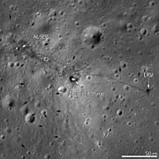
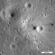
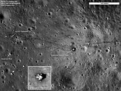
The rover used on Apollo 15 was left at Hadley-Apennine ( 26°06′N 3°39′E / 26.10°N 3.65°E ). The rover used on Apollo 16 was left at Descartes ( 8°59′S 15°31′E / 8.99°S 15.51°E ). The rover used on Apollo 17 was left at Taurus-Littrow ( 20°10′N 30°46′E / 20.16°N 30.76°E ) and was seen by the Lunar Reconnaissance Orbiter during passes in 2009 and 2011. In 2020 the State of Washington designated the flown rovers as historic landmarks.
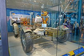
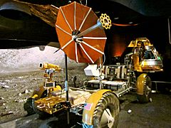
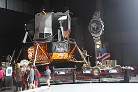
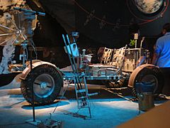
Since only the upper stages of the lunar excursion modules could return to lunar orbit from the surface, the vehicles, along with the lower stages were abandoned. As a result, the only lunar rovers on display are LRV-4, test vehicles, trainers, and mock-ups.
- Lunar Roving Vehicle 4 (LRV-4) is on display at the Kennedy Space Center Visitors Complex in Cape Canaveral, Florida.
- The Engineering Mockup, intended to design and integrate subsystems, is on display at the Museum of Flight in Seattle, Washington.
- The Qualification Test Unit, designed to study integration of all LRV subsystems, is on display at the National Air and Space Museum in Washington, D.C.
- The Vibration Test Unit, intended to study durability and handling of launch stresses, is on display in the Davidson Saturn V Center at the U.S. Space & Rocket Center in Huntsville, Alabama.
- The 1-gravity trainer is on display at the Johnson Space Center in Houston, Texas.
As mentioned before, additional test units were built, like a static model, two 1/6 gravity models, a mass model.
- Lunar Roving Vehicles, test vehicles and trainers
-
LRO image of Apollo 15 site, LRV-1 is near the right edge
-
LRO image of Apollo 16 site, LRV-2 is near the right edge
-
LRO image of Apollo 17 site, LRV-3 is in the lower right
-
LRV 1-gravity trainer, Space Center Houston
-
LRV engineering mockup, Museum of Flight
-
LRV Vibration Test Unit, U.S. Space & Rocket Center
-
LRV Qualification Test Unit, National Air and Space Museum
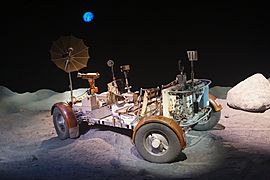
Replicas of rovers are on display at the Johnson Space Center in Houston, Texas, the Kennedy Space Center Visitors Complex in Cape Canaveral, Florida, the National Museum of Naval Aviation in Pensacola, Florida, the Evergreen Aviation & Space Museum in McMinnville, Oregon, the Kansas Cosmosphere and Space Center in Hutchinson, Kansas and the Omega Museum in Biel, Switzerland. A replica on loan from the Smithsonian Institution is on display at the Mission: Space attraction at Epcot at the Walt Disney World Resort near Orlando, Florida.
Images for kids
-
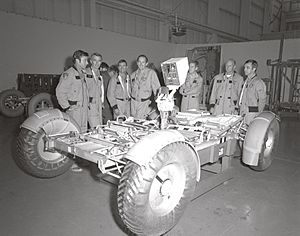
Apollo 16 astronauts in the 1-g trainer
-
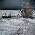
John Young works at the LRV near the LM Orion on Apollo 16 in April 1972.
-
Apollo 15 – Commander David Scott drives the Rover near the LM Falcon
-
Lunar rover on Space Achievement Decade Issue of 1971
-
Eugene Cernan test drives the Apollo 17 lunar rover shortly after unloading it from the LM Challenger
-
Rover replica on display at Epcot
See also
 In Spanish: Lunar Roving Vehicle para niños
- List of artificial objects on the Moon
- Lunar Terrain Vehicle
- Modular Equipment Transporter


