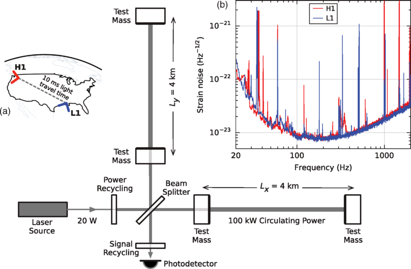
Image: Simplified diagram of an Advanced LIGO detector
Description: Simplified diagram of an Advanced LIGO detector (not to scale). A gravitational wave propagating orthogonally to the detector plane and linearly polarized parallel to the 4-km optical cavities will have the effect of lengthening one 4-km arm and shortening the other during one half-cycle of the wave; these length changes are reversed during the other half-cycle. The output photodetector records these differential cavity length variations. While a detector’s directional response is maximal for this case, it is still significant for most other angles of incidence or polarizations (gravitational waves propagate freely through the Earth). Inset (a): Location and orientation of the LIGO detectors at Hanford, WA (H1) and Livingston, LA (L1). Inset (b): The instrument noise for each detector near the time of the signal detection; this is an amplitude spectral density, expressed in terms of equivalent gravitational-wave strain amplitude. The sensitivity is limited by photon shot noise at frequencies above 150 Hz, and by a superposition of other noise sources at lower frequencies [47]. Narrow-band features include calibration lines (33–38, 330, and 1080 Hz), vibrational modes of suspension fibers (500 Hz and harmonics), and 60 Hz electric power grid harmonics.
Title: Simplified diagram of an Advanced LIGO detector
Credit: Observation of Gravitational Waves from a Binary Black Hole Merger B. P. Abbott et al. (LIGO Scientific Collaboration and Virgo Collaboration) Phys. Rev. Lett. 116, 061102 doi:10.1103/PhysRevLett.116.061102
Author: Abbott, B. P. et al.
Usage Terms: Creative Commons Attribution 3.0
License: CC BY 3.0
License Link: http://creativecommons.org/licenses/by/3.0
Attribution Required?: Yes
Image usage
The following page links to this image:


