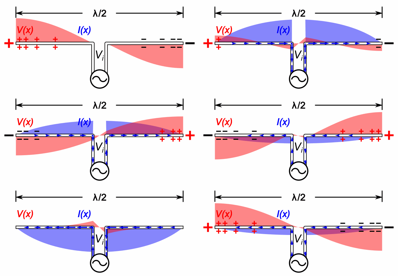
Image: Dipole antenna standing waves animation 6 - 5fps
Description: Animation showing standing waves on a half-wave dipole antenna driven by a sinusoidal voltage Vi from a radio transmitter at its resonant frequency. The oscillating voltage pushes the electrons back and forth along the two metal rods that make up the antenna, creating oscillating currents (blue arrows) in the antenna, charging its ends alternately positive (+) and negative (-). Since at this frequency the antenna is a half wavelength (λ/2) long, a sinusoidal wave of voltage or current takes exactly one cycle to make the round trip from one end of the antenna to the other and back, so the reflected waves reinforce each other. The antenna acts like an electronic resonater. Waves of current and voltage reflecting back and forth between the ends of the rods interfere to form standing waves, which radiate radio waves into space. The waves are shown graphically by bars of color (red for voltage V(x) and blue for current I(x)) whose width at each point is proportional to the amplitude of the wave at that point. The blue arrows show the direction of conventional current, flow of positive charge. The electrons oscillating back and forth in the antenne move in a direction opposite to the arrows. The action is shown slowed down enormously; the currents in an actual antenna oscillate back and forth 20 thousand to one billion times per second. This image differs from my previous animation Dipole antenna standing waves animation 1-10fps.gif and most graphs of the standing waves shown in antenna textbooks in that it shows the effect of the driving voltage on the standing waves. The transmission line applies a voltage Vicosωt{\displaystyle V_{i}\cos \omega t} between the two antenna elements, driving the oscillations. The energy from this current provides the energy lost in the antenna' s radiation resistance which represents the energy radiated as radio waves. Since the antenna is fed at its resonant frequency, the input voltage is in phase with the current (blue bar), so the antenna presents a pure resistance to the feedline. Dipoles have relatively high Q factor so the amount of energy stored in the standing waves is large compared to the energy added each cycle by the feedline, the feed voltage just represents a small perturbation to the standing waves. This is why the voltage standing wave is much larger than the voltage step at the feedline. Since the standing waves are storing energy, not transporting power, the current in them is not in phase with the voltage but 90° out of phase
Title: Dipole antenna standing waves animation 6 - 5fps
Credit: Own work
Author: Chetvorno
Usage Terms: Creative Commons Zero, Public Domain Dedication
License: CC0
License Link: http://creativecommons.org/publicdomain/zero/1.0/deed.en
Attribution Required?: No
Image usage
The following page links to this image:


