Electric power transmission facts for kids
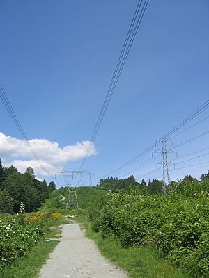
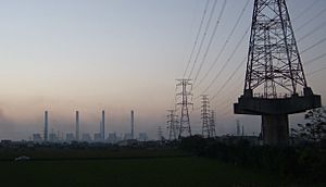
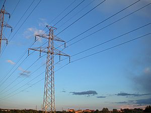
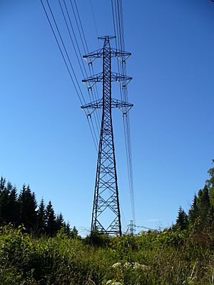
Electric power transmission is one process in the transmitting of electricity to consumers. The term refers to the bulk transfer of electrical power from place to place. Typically, power transmission is between the power plant and a substation near a populated area. Electric power distribution is the delivery from the substation to the consumers. Due to the large amount of power involved, transmission normally takes place at high voltage (110 kV or above).
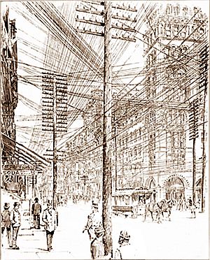
Electricity is usually transmitted over long distance through overhead power transmission lines. Underground power transmission is used only in densely populated areas (such as large cities) because of the high cost of installation and maintenance and because the power losses increase dramatically compared with overhead transmission unless superconductors and cryogenic technology are used.
A power transmission system is sometimes referred to colloquially as a "grid"; however, for reasons of economy, the network is rarely a true grid. Redundant paths and lines are provided so that power can be routed from any power plant to any load center, through a variety of routes, based on the economics of the transmission path and the cost of power.
Contents
Overhead transmission
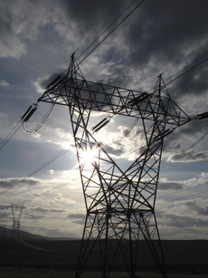
High-voltage overhead conductors are not covered by insulation. The conductor material is nearly always an aluminum alloy, made into several strands and possibly reinforced with steel strands. Copper was sometimes used for overhead transmission, but aluminum is lighter, yields only marginally reduced performance and costs much less. Overhead conductors are a commodity supplied by several companies worldwide. Improved conductor material and shapes are regularly used to allow increased capacity and modernize transmission circuits. Conductor sizes range from 12 mm2 (#6 American wire gauge) to 750 mm2 (1,590,000 circular mils area), with varying resistance and current-carrying capacity. Thicker wires would lead to a relatively small increase in capacity due to the skin effect (which causes most of the current to flow close to the surface of the wire). Because of this current limitation, multiple parallel cables (called bundle conductors) are used when higher capacity is needed. Bundle conductors are also used at high voltages to reduce energy loss caused by corona discharge.
Today, transmission-level voltages are usually considered to be 110 kV and above. Lower voltages, such as 66 kV and 33 kV, are usually considered subtransmission voltages, but are occasionally used on long lines with light loads. Voltages less than 33 kV are usually used for distribution. Voltages above 765 kV are considered extra high voltage and require different designs compared to equipment used at lower voltages.
Since overhead transmission wires depend on air for insulation, the design of these lines requires minimum clearances to be observed to maintain safety. Adverse weather conditions, such as high wind and low temperatures, can lead to power outages. Wind speeds as low as 23 knots (43 km/h) can permit conductors to encroach operating clearances, resulting in a flashover and loss of supply. Oscillatory motion of the physical line can be termed gallop or flutter depending on the frequency and amplitude of oscillation.
Underground transmission
Electric power can also be transmitted by underground power cables instead of overhead power lines. Underground cables take up less right-of-way than overhead lines, have lower visibility, and are less affected by bad weather. However, costs of insulated cable and excavation are much higher than overhead construction. Faults in buried transmission lines take longer to locate and repair. Underground lines are strictly limited by their thermal capacity, which permits less overload or re-rating than overhead lines. Long underground AC cables have significant capacitance, which may reduce their ability to provide useful power to loads beyond 50 miles (80 kilometres). DC cables are not limited in length by their capacitance.
History
In the early days of commercial electric power, transmission of electric power at the same voltage as used by lighting and mechanical loads restricted the distance between generating plant and consumers. In 1882, generation was with direct current (DC), which could not easily be increased in voltage for long-distance transmission. Different classes of loads (for example, lighting, fixed motors, and traction/railway systems) required different voltages, and so used different generators and circuits.
Due to this specialization of lines and because transmission was inefficient for low-voltage high-current circuits, generators needed to be near their loads. It seemed, at the time, that the industry would develop into what is now known as a distributed generation system with large numbers of small generators located near their loads.
The transmission of electric power with alternating current (AC) became possible after Lucien Gaulard and John Dixon Gibbs built what they called the secondary generator, an early transformer provided with 1:1 turn ratio and open magnetic circuit, in 1881.
The first long distance AC line was 34 kilometres (21 miles) long, built for the 1884 International Exhibition of Turin, Italy. It was powered by a 2000 V, 130 Hz Siemens & Halske alternator and featured several Gaulard secondary generators with their primary windings connected in series, which fed incandescent lamps. The system proved the feasibility of AC electric power transmission on long distances.
A very first operative AC line was put into service in 1885 in via dei Cerchi, Rome, Italy, for public lighting. It was powered by two Siemens & Halske alternators rated 30 hp (22 kW), 2000 V at 120 Hz and used 19 km of cables and 200 parallel-connected 2000 V to 20 V step-down transformers provided with a closed magnetic circuit, one for each lamp. Few months later it was followed by the first British AC system, which was put into service at the Grosvenor Gallery, London. It also featured Siemens alternators and 2400 V to 100 V step-down transformers – one per user – with shunt-connected primaries.
Working from what he considered an impractical Gaulard-Gibbs design, electrical engineer William Stanley, Jr. developed what is considered the first practical series AC transformer in 1885. Working with the support of George Westinghouse, in 1886 he installed demonstration transformer based alternating current lighting system in Great Barrington, Massachusetts. Powered by a steam engine driven 500 V Siemens generator, voltage was stepped down to 100 Volts using the new Stanley transformer to power incandescent lamps at 23 businesses along main street with very little power loss over 4000 feet. This practical demonstration of a transformer and alternating current lighting system would lead Westinghouse to begin installing AC based systems later that year.
1888 saw designs for a functional AC motor, something these systems had lacked up till then. These were induction motors running on polyphase current, independently invented by Galileo Ferraris and Nikola Tesla (with Tesla’s design being licensed by Westinghouse in the US). This design was further developed into the modern practical three-phase form by Mikhail Dolivo-Dobrovolsky and Charles Eugene Lancelot Brown. Practical use of these types of motors would be delayed many years by development problems and the scarcity of poly-phase power systems needed to power them.
The late 1880s and early 1890s would see a financial merger of many smaller electric companies into a few larger corporations such as Ganz and AEG in Europe and General Electric and Westinghouse Electric in the US. These companies continued to develop AC systems but the technical difference between direct and alternating current systems would follow a much longer technical merger. Due to innovation in the US and Europe, alternating current's economy of scale with very large generating plants linked to loads via long distance transmission was slowly being combined with the ability to link it up with all of the existing systems that needed to be supplied. These included single phase AC systems, poly-phase AC systems, low voltage incandescent lighting, high voltage arc lighting, and existing DC motors in factories and street cars. In what was becoming a universal system, these technological differences were temporarily being bridged via the development of rotary converters and motor-generators that would allow the large number of legacy systems to be connected to the AC grid. These stopgaps would slowly be replaced as older systems were retired or upgraded.
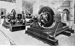
The first transmission of single-phase alternating current using high voltage took place in Oregon in 1890 when power was delivered from a hydroelectric plant at Willamette Falls to the city of Portland 14 miles downriver. The first three-phase alternating current using high voltage took place in 1891 during the international electricity exhibition in Frankfurt. A 15,000 V transmission line, approximately 175 km long, connected Lauffen on the Neckar and Frankfurt.
Voltages used for electric power transmission increased throughout the 20th century. By 1914, fifty-five transmission systems each operating at more than 70,000 V were in service. The highest voltage then used was 150,000 V. By allowing multiple generating plants to be interconnected over a wide area, electricity production cost was reduced. The most efficient available plants could be used to supply the varying loads during the day. Reliability was improved and capital investment cost was reduced, since stand-by generating capacity could be shared over many more customers and a wider geographic area. Remote and low-cost sources of energy, such as hydroelectric power or mine-mouth coal, could be exploited to lower energy production cost.
The rapid industrialization in the 20th century made electrical transmission lines and grids a critical infrastructure item in most industrialized nations. The interconnection of local generation plants and small distribution networks was greatly spurred by the requirements of World War I, with large electrical generating plants built by governments to provide power to munitions factories. Later these generating plants were connected to supply civil loads through long-distance transmission.
Bulk power transmission
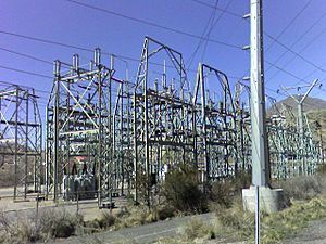
Engineers design transmission networks to transport the energy as efficiently as feasible, while at the same time taking into account economic factors, network safety and redundancy. These networks use components such as power lines, cables, circuit breakers, switches and transformers. The transmission network is usually administered on a regional basis by an entity such as a regional transmission organization or transmission system operator.
Transmission efficiency is greatly improved by devices that increase the voltage (and thereby proportionately reduce the current), in the line conductors, thus allowing power to be transmitted with acceptable losses. The reduced current flowing through the line reduces the heating losses in the conductors. According to Joule's Law, energy losses are directly proportional to the square of the current. Thus, reducing the current by a factor of two will lower the energy lost to conductor resistance by a factor of four for any given size of conductor.
The optimum size of a conductor for a given voltage and current can be estimated by Kelvin's law for conductor size, which states that the size is at its optimum when the annual cost of energy wasted in the resistance is equal to the annual capital charges of providing the conductor. At times of lower interest rates, Kelvin's law indicates that thicker wires are optimal; while, when metals are expensive, thinner conductors are indicated: however, power lines are designed for long-term use, so Kelvin's law has to be used in conjunction with long-term estimates of the price of copper and aluminum as well as interest rates for capital.
The increase in voltage is achieved in AC circuits by using a step-up transformer. HVDC systems require relatively costly conversion equipment which may be economically justified for particular projects such as submarine cables and longer distance high capacity point-to-point transmission. HVDC is necessary for the import and export of energy between grid systems that are not synchronized with each other.
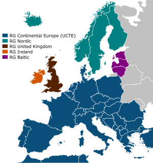
A transmission grid is a network of power stations, transmission lines, and substations. Energy is usually transmitted within a grid with three-phase AC. Single-phase AC is used only for distribution to end users since it is not usable for large polyphase induction motors. In the 19th century, two-phase transmission was used but required either four wires or three wires with unequal currents. Higher order phase systems require more than three wires, but deliver little or no benefit.
The price of electric power station capacity is high, and electric demand is variable, so it is often cheaper to import some portion of the needed power than to generate it locally. Because loads are often regionally correlated (hot weather in the Southwest portion of the US might cause many people to use air conditioners), electric power often comes from distant sources. Because of the economic benefits of load sharing between regions, wide area transmission grids now span countries and even continents. The web of interconnections between power producers and consumers should enable power to flow, even if some links are inoperative.
The unvarying (or slowly varying over many hours) portion of the electric demand is known as the base load and is generally served by large facilities (which are more efficient due to economies of scale) with fixed costs for fuel and operation. Such facilities are nuclear, coal-fired or hydroelectric, while other energy sources such as concentrated solar thermal and geothermal power have the potential to provide base load power. Renewable energy sources, such as solar photovoltaics, wind, wave, and tidal, are, due to their intermittency, not considered as supplying "base load" but will still add power to the grid. The remaining or 'peak' power demand, is supplied by peaking power plants, which are typically smaller, faster-responding, and higher cost sources, such as combined cycle or combustion turbine plants fueled by natural gas.
Long-distance transmission of electricity (hundreds of kilometers) is cheap and efficient, with costs of US$0.005–0.02 per kWh (compared to annual averaged large producer costs of US$0.01–0.025 per kWh, retail rates upwards of US$0.10 per kWh, and multiples of retail for instantaneous suppliers at unpredicted highest demand moments). Thus distant suppliers can be cheaper than local sources (e.g., New York often buys over 1000 MW of electricity from Canada). Multiple local sources (even if more expensive and infrequently used) can make the transmission grid more fault tolerant to weather and other disasters that can disconnect distant suppliers.
Long-distance transmission allows remote renewable energy resources to be used to displace fossil fuel consumption. Hydro and wind sources cannot be moved closer to populous cities, and solar costs are lowest in remote areas where local power needs are minimal. Connection costs alone can determine whether any particular renewable alternative is economically sensible. Costs can be prohibitive for transmission lines, but various proposals for massive infrastructure investment in high capacity, very long distance super grid transmission networks could be recovered with modest usage fees.
Related pages
Images for kids
-
Five-hundred kilovolt (500 kV) Three-phase electric power Transmission Lines at Grand Coulee Dam; four circuits are shown; two additional circuits are obscured by trees on the far right; the entire 7079 MW nameplate generation capacity of the dam is accommodated by these six circuits.
-
A 115 kV subtransmission line in the Philippines, along with 20 kV distribution lines and a street light, all mounted in a wood subtransmission pole
See also
 In Spanish: Transmisión de energía eléctrica para niños


